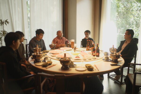
I met up with some old friends who's either in VFX or gaming industry. A lot of interesting discussions there. Old traditional VFX industry is not doing very well here (I guess probably it's the same everywhere), and some of our friends wanted to move to making games, likely in a small studio, which can bring more expressive storytelling, and also a smaller team can mean everyone felt that the project "belong to them" instead of feeling like a cog in a wheel. This mentality has been stronger overall compared to the previous year. Looking forward to see how this would turn out.
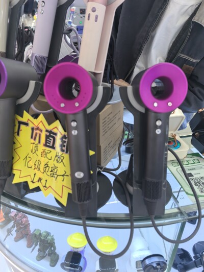
I finally visited Huaqiangbei electronics market again! Last time it's like 7 or 8 years ago. The place is more organized now, and when I check those consumer devices and OEMs, those have even better services for packaging design and marketing overseas. And guess how much these "Dyson" hairdryers cost :D (15$ and 9$ each, and they now have their own brand with original designs, which costs like 20$ for a whole set, all the same control logic and same turbine blower)
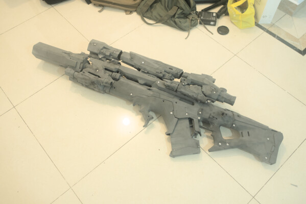
Also... Some people may already know that I was doing a 3d print project on the side which is this prop gun I designed, the 3d print was finished when I was in Shenzhen, now I got it back, and it was Awesome, just need to spend some time spray paint it and assemble and do electronics and programming the RP2040 and etc etc... It's close to 10kg because I was dumb and didn't save enough materials, but at least it's sturdy. Mentin suggested that I should post this to Blender Artists forum, maybe I'll do it this weekend, because I still got a ton of work stuff on Blender side needs to be finished lol.
BTW this was the project that prompted a potential mesh CAD research that I also brought up to Francisco in Shenzhen Briefly. So far don't have time to go deeper tho. Maybe I'll do something with it next year. AND writing papers? hummmm...
Pictorial works
Hurricane Launcher v2 Prop
Comic: Blowback
Blowback: Extra Artworks
The Continent
Comic: Rescuer
Comic: Flight 811
Utility Tools
Our Paint v0.5
A Intelligent Mesh Structure
Retro Cam
Digital 8mm Video Camera
LaGUI
Line Art
LaMDWiki
GPencil Font Plugin
Over The Edge NEW
List of Issues
Others
Store
Old Literature
About
STATUS: Finished with mechanical. Electric components pending.
This is an updated design based on the Hurricane Launcher concept I did last year for the comic and a similar rifle design from this more recent piece. The intention is to make a 3d printable model out of it.
Note: Projectile launching structure is NOT planned or implemented.
At this point I started doing structural drawings for internal elements and fastening elements. Here the main solenoid, chamber tube and the stock structure is depicted.
The battery compartment and fastening structure for the middle body. The structure behind the ejection port is quite slim, this requires extra support in the front portion of the middle body (currently done via screw in the front of the chamber), and the use of extra thick shell.
Redesigned the installation structure for the main trigger. In the first a spring pusher is installed, then the trigger body is pushed downwards and locked in place.
Rough structure of the decorative scope and the forebody. The middle scope has to be installed to stop the upper forebody from bending downwards. If not installed, a placeholder hook must be installed in the same place to stop the bending moment.
Spent quite some time to take care of the subdivision surface of the shell. Since there's tons of geometry elements that are used to control curvature, this process is not particularly efficient, especially when you need to fine tune/modify some forms, however looptools can help with features that are mostly planar/linear.
Volume approximation after adding ~5mm shell thickness. Final volume of the model should be close to or a bit over this value. Main problems:
Final product can be quite heavy. (Density of PA6 is around 1.13g/cm^3, and bulk weight of battery and solenoid needs to be added on top)
Unsure if the current fastening structure can hold the center line, considering the weight and parting structure of the front section. Might need additional fastening structure alongside the axial direction.
Cost of manufacturing can be quite high, but should be within budget.
A particular problem in this stage of modeling is to create a inner shell for the shell that's already modeled with subdiv. This portion is not visually complex but took quite some time to do. Directly calling solidify on this kind of surfaces will result in very long post-processing time and relatively bad surface quality for the inner shell as well as uneven thickness. Afterwards the remaining surfaces are all shelled out manually portions by portion and connected together afterwards, it then gave better result and saved more time.
Continuing on the structure of the decorative scope. In principle it's OK to print these as a unibody, however by splitting them into two or three parts, more screws can be hidden, as well as allowing shorter hex driver shaft when assembling, and exposed screws can be placed at visually pleasing locations.
Finished assembling. Some main issues on the mechanical aspect:
During final adjustments to the big screw holder, the mesh was accidentally scaled in edit mode, which created a bunch of small interference (they share the same screw post mesh). Luckily the problem isn't significant, and they are all mitigated by grinding.
M3 clamping screw seems to have a different actual dimension on the head of the nut side than specified, or I didn't leave enough clearances, which means some holes doesn't fit quite as nicely, visually passable tho.
Did not reliably count all the screws. Some positions doesn't have screws of ideal lengths to be put in.
During boolean restructuring, some geometry features can be lost. Specifically in this case, the radial nut holder hole on the front of smoke pipe was missing, and the screw holes and one small bridging feature for the aft pipe connector on the display device component was missing. Not visually apparent but not ideal either. After investigation, it was caused by failed manifold boolean due to exact boolean upon base mesh on a higher subdiv level creating non-manifold geometries, which did not happen in lower subdiv levels.
Long thin holes can't be cleaned (to a point where it's free of powder) easily. A small grinder/drill can then create viable structure to still insert light stripes, but not very ideal. Good enough if looked from far away tho.
The structure is only designed in a way that it can be assembled, but the ease of assembling is not thought about enough. This is especially true for this project because a lot of structures are interlocked for overall rigidity.
No existing plastic equipment case to put this assembly without disassembling portions of it. So far the front-most pipe sheath and the battery box needs to be disassembled before putting into the a box. Luckily neither of those are too complex.
Overall I'm very satisfied with the SLS process. Forming and deformation control is top notch. I didn't have any print-related assembling issues with this set of model. Some thin-walled parts (like the shell of the under portion of front scope didn't have adequate centering pulling force) have slight deformations, but can be avoided by design. And even so the warping is only slightly visible on the seam where two parts meet.
This project used Gaahleri branded water based paint (which is basically acrylic paint with less viscosity) for priming and all coloring.
Matte and semi-matte-gloss surface finish was chosen for this project. This ensures natural and smooth looking gradient on various lighting conditions.
It's best to spray one layer of primer and then sand the part before doing the actual priming and coloring (though it's a bit wasteful), that should give a much better surface finish. SLS process will leave a fuzzy surface to the touch, can also just leave it as is.
Water based primer has satisfactory opaqueness, similar to gouache. When the sprayed paint collected on the ground, it formed a dust-like layer instead of hardened paint surface, which can be easily cleaned.
Yellow/Orange can't cover the color underneath very well (although advertised as high opaqueness), viscosity is low and will pool in concave locations. The paint itself is rich and vibrant. It's best to be painted over white instead of literally anything that has a shade. Usually takes 2 or 3 passes to get a uniform coverage due to pooling. Did not try mixing with white primer, in theory it should give better opaqueness (like watercolor + titanium white).
Very slight solvent odor when not wearing mask
Satisfactory drying time. Mostly dry to touch in maybe 5 mins in the heating cabinet at 60C.
Primer is not very resistant to scratches or impact. During the painting operation this is somewhat unavoidable. Another reason is that I have a small heating cabinet, parts can sometimes touch each other.
Varnish isn't "super durable" either. It's better than primer tho. Because of the weight of the entire model, when accidentally scratched or impacted stuff, it can still leave a mark, however this can give a natural weathering after using it for a long time.
Masking is such an inefficient process. A lot of times I think we can simply mask small parts and paint with a brush directly. If needs spray painting, then indeed a lot of things has to be masked each time.
Green-colored masking tape is not recommended (unless spray paint immediately after masking), regular yellow masking tape doesn't seem to break the paint layer underneath. Always spray paint quickly after masking otherwise risk leaking.
Regular sticker paper laser printed for pattern cutting template is also not recommended, it's too sticky and will leave a bit residue, and it also suffers from the leaking problem like the green one. All leaky spray paint patterns can be fixed with a paint brush easily afterwards.
The structure of windings on the main solenoid was different than expected. Previously I was expecting the solenoid to be wired as Common/Forward/Backward, however after inspection, it is apparently wired as a 3 phase system (like a brush-less induction motor), this invalidated my initial drive scheme. Should not expect regular motor driver board to rapidly switch direction on full power, and those driver units are typically bigger than the space reserved for the solenoid driver circuit.
When switching on the power battery, there will be a massive surge that immediately fires the DC-DC converter (and potentially other devices, if connected), these modules doesn't have surge/ESD protections.
For the second issue, I will attempt to connect a serial power resistor to limit the current and a parallel 26/28V TVS diode and check whether that's reliable. The first issue is probably gonna be unsolvable in the scope of this project, because the mechanical restrictions.
Other parts of the circuit doesn't seem to have any significant problems.
The form for those decorative pipes still needs adjustment, mainly inadequate curving radius which needs internal support, and also micro adjustments to pipe lengths.
Used 25 Ohms power resistor and 26V TVS diode, still burned the small DC-DC module, but I found this 40V tolerant module worked just fine with this setup, so that's one problem solved :D
The factory now will give me the controller board for the main solenoid, and it seems to be able to fit, so I'll see whether this thing can be done when it's arrived. The driver board comes with hall effect sensor board, it might be need to detect the position of the magnet bar, there might not be enough space to put that in at the front of the solenoid in the tube, but it may fit if I remove the dynamic shell ejection port. We'll see how it goes then :)
Actually these pictures are in AdobeRGB color space, and the uploaded color is wrong (ICC profile is not transferred to the final image after the server compressed them, I forgot this problem). I'll update these pictures later. (done)
Except the second picture below is by Helios 44-2 at f/2.8, other pictures are Sirui 75mm T1.2 set at T1.4.
Last two pictures are Zhongyi 20T1 set at about 1.4
Looks like I'm not that experienced with contrasting accent color lighting so the blue ended up washing out the warm tone in a few shots... I'll try putting them more on rim locations next time.
Additional explanation of what's going on with the electronics part of this model:
Lights and wiring to switches are all verified to work.
Installation of the rear of the device includes a rotation step of the shell on top of the main solenoid. the structure of the wire slot wasn't taking this into account, and due to the tight fit structure, there aren't much extra space for wires to pass through. So the main controls in the rear failed to be connected in the end.
Due to the consideration of the structure integrity, the switch holder was made directly on the shell as a unibody, it's theoretically possible to assemble, but not very easily accessible. Additionally the mode switch requires some instant glue to fix the articulating structure, one side of the mode switch was then accidentally glued in place.
Overall, the appearance is not affected, but it is also very hard to connect the main control. So the circuit part of this project is not continued.
In future projects, fully kinematic (only manually movable structure) designs will be preferred, and if there will be electrified designs in the end, the structure should be designed in a way where wire compartments can be opened after assembling, and switch assemblies should be separate structures that simplifies wiring.